
Optimizing Custom FFT’s Speed on STM32
In this post, we’ll take the STM32 FFT algorithm from my blog “Writing Your Own FFT in Python and STM32” (link below) and focus on improving its execution speed. The goal is to minimize the number of clock cycles required to perform the FFT. To achieve this, we’ll remove unnecessary calculations, precompute the bit-reversal lookup table, enable compiler optimizations, activate the cache, and place buffers in faster memory. We’ll evaluate how each of these changes impacts performance, and compare our optimized algorithm to the CMSIS DSP library’s FFT.

DWT + ITM + SWO and MCU Cycle Counting
In this post, we’ll explore several powerful debugging and profiling tools available on ARM Cortex-M7 microcontrollers. Specifically, we’ll use the DWT (Data Watchpoint and Trace) unit to perform precise cycle counting, and send this timing information through the ITM (Instrumentation Trace Macrocell), which transmits it to the debugger over the SWO (Single Wire Output) interface. These features allow developers to measure algorithm execution times with minimal overhead, which is especially useful when optimizing performance-critical code like FFTs or control loops. Rather than a formal tutorial, this post serves as a working notebook of how I’ve implemented and used these features in real projects, with enough detail to help others get started quickly.
Writing Your Own FFT in Python and STM32
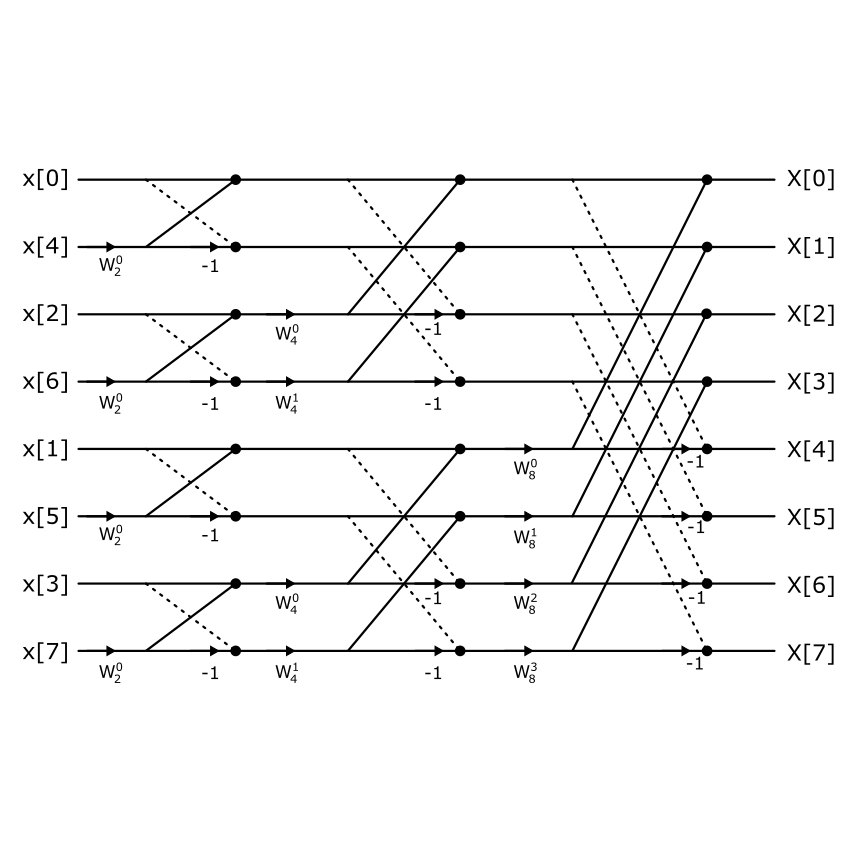
In this post, we’ll be diving into the process of writing our own custom Fast Fourier Transform (FFT) implementation from scratch. The FFT is a foundational algorithm in digital signal processing, used to convert time-domain signals into their frequency-domain representation. While many libraries and tools offer ready-made FFT functions, coding one yourself is a great way to build a deeper understanding of how it works under the hood.
I’ll start by lightly covering a bit of the theory but try and discuss implementing the algorithm itself in more detail. From there, we’ll jump into writing the code in Python, which allows us to test and visualize the results quickly. Then, we’ll bring it down to the hardware level by implementing the same FFT logic on an STM32 microcontroller, where things like memory usage and performance really start to matter.
The goal here isn’t to create the fastest or most optimized FFT, but to build something simple.

Numerically Controlled Oscillator in Python and STM32
In this post, I’ll cover the basics of creating a Numerically Controlled Oscillator (NCO) from the ground up. An NCO is a digital signal generator that uses a phase accumulator and a waveform lookup table to produce precise, periodic signals—usually sine, square, or triangle waves. These waveforms are generated entirely in the digital domain, making NCOs extremely useful in systems where analog components are limited or where digital precision is required.
NCOs are widely used in a variety of applications, including digital communications, frequency synthesis, software-defined radio (SDR), and audio signal generation. Their ability to generate stable, tunable frequencies with minimal hardware makes them a valuable tool in embedded and signal processing systems.
We’ll begin by modeling the NCO in Python. This lets us explore and visualize the underlying concepts like phase resolution, tuning words, and waveform table indexing without worrying about hardware limitations. Once the behavior is well understood, we’ll transition to implementing the NCO in C on an STM32 microcontroller, where we’ll focus on efficient fixed-point arithmetic and real-time constraints.