Voltage-Dependent Voltage Source (e)
In this post, we’ll take a look at a sometimes overlooked SPICE element: the voltage-dependent voltage source. This is a powerful component that can be used to quickly simulate the ideal behavior of circuits, specifically for modeling ideal operational amplifiers. This is especially useful for when you're not yet ready to dive into real SPICE models. Using LTspice, we’ll demonstrate how to use the voltage-dependent voltage source (represented by the symbol "E" in LTspice) to emulate an ideal op-amp. We’ll then gradually reduce the gain of the voltage-controlled voltage source to observe how the op-amp’s open-loop gain influences the output signal.
Additional Resources:
Design with Operational Amplifiers and Analog Integrated Circuits - Sergio Franco
In short, a voltage-dependent voltage source outputs a voltage equal to the difference between its positive and negative input terminals, multiplied by a user-defined gain. For example, if the input terminals are labeled Vinp and Vinm, then the output voltage Vout is given by:
Vout = Gain × ( Vinp - Vinm )
In some configurations, the output of a voltage-dependent voltage source can be differential, meaning it has both a positive and a negative output terminal. In that case, the equation becomes:
Vout = Voutp - Voutm = Gain × ( Vinp - Vinm )
However, when using a voltage-dependent voltage source to model an operational amplifier, we typically use a differential input but a single-ended output. That means we define only one output terminal (Voutp), and the other (Voutm) is tied to 0 V. So in this case, the expression simplifies to:
Vout = Voutp = Gain × ( Vinp - Vinm )
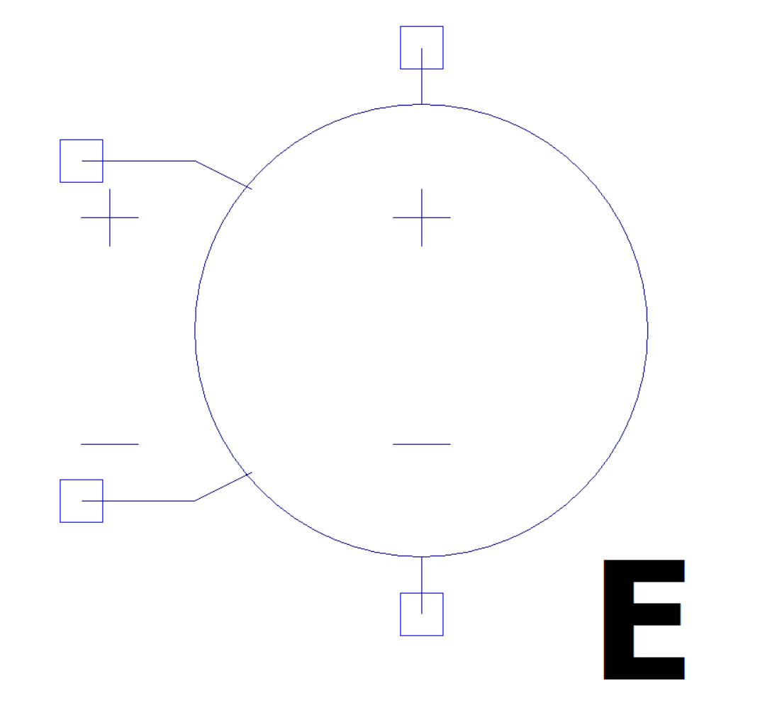
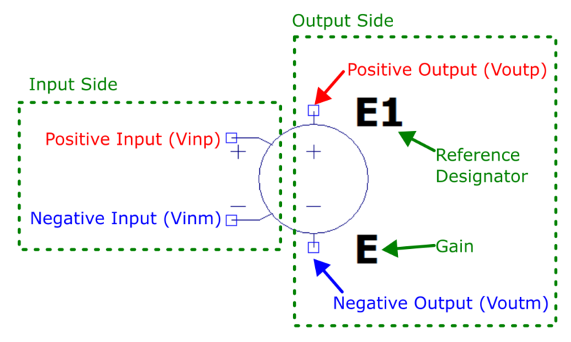
The image below shows the symbol for the voltage-dependent voltage source in LTspice. It highlights the pins for the positive and negative inputs, the positive and negative outputs, the gain, and the reference designator (also known in LTspice as InstName). The reference designator is simply the identifier LTspice assigns to each instance of the symbol, it auto-increments as you place more of them on the schematic (e.g., E1, E2, E3…). I want to draw attention to this because the reference designator can look very similar to the gain parameter, especially since both start with the letter "E". So when setting the gain of the voltage-dependent voltage source, be careful to change the numeric value next to the “E” symbol, not the reference designator itself. Otherwise, you may unintentionally rename the component rather than adjust its behavior.
Basic Simulation Example
We’ll start by creating a simple simulation to demonstrate:
Where to find the voltage-dependent voltage source
How to use it in a circuit
First, open LTspice and create a new schematic. Then, go to Edit >> Component from the top menu. This will open the Select Component Symbol dialog.
In the dialog, scroll through the list or use the search bar to find the component named “e”. This is the symbol for the voltage-dependent voltage source. Select it and place it onto your schematic.

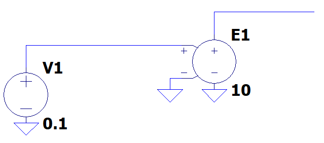
Next we will connect the positive input to a voltage source set to 0.1V and connect the negative input source to ground. We will also connect the negative output pin to ground and set the gain of the voltage-dependent voltage source to 10.
The easiest way to demonstrate how the voltage-dependent voltage source works is to run a DC operating point simulation and display the resulting voltages directly on the schematic.
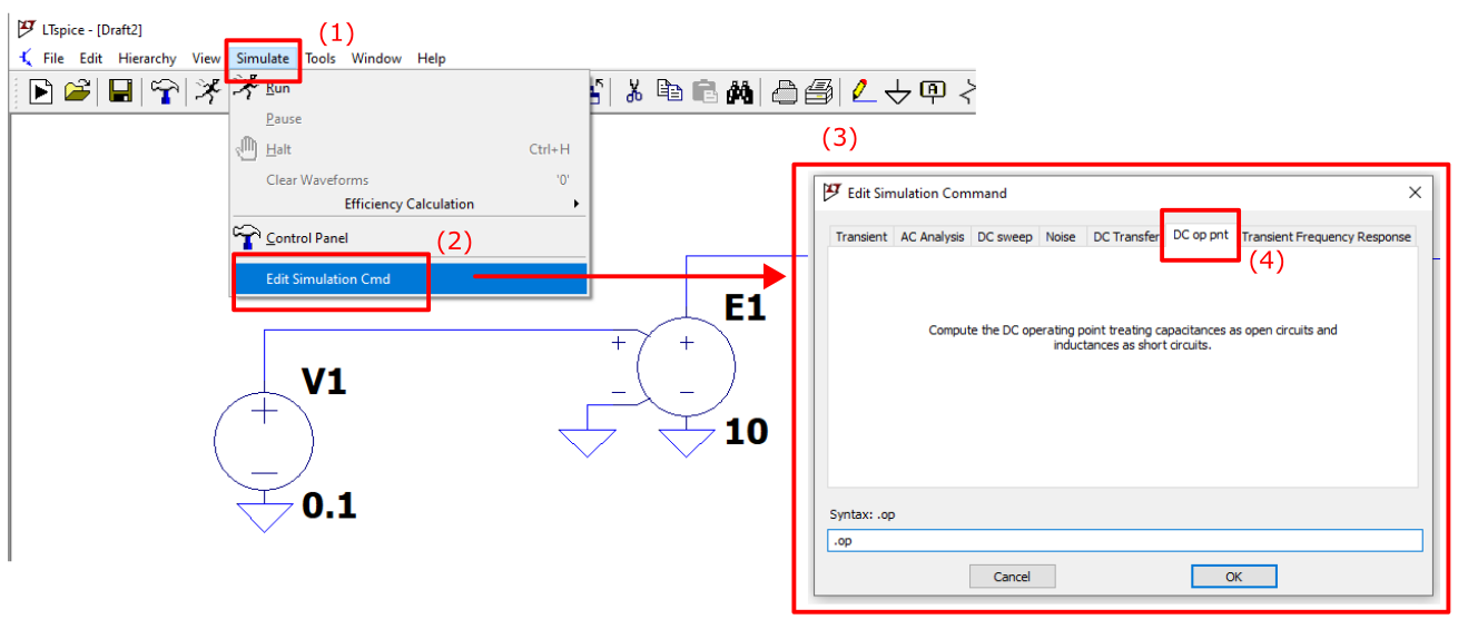
To setup a DC operating point simulation in LTspice go to Simulate >> Edit Simulation Cmd from the top menu. This will open the Edit Simuation Command dialog.
In the dialog, find the tab labelled “DC op pnt”. This is the DC operating point simulation. Select it and place it onto your schematic.
Run the simulation.
Next we will add .op labels to our schematic to easily see the DC voltages at each node. To add these labels, right click on a wire and select “Place .op Data Label” from the menu.
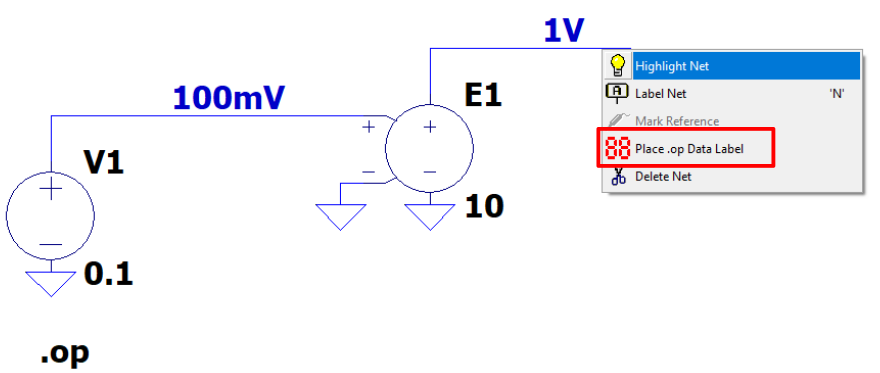
From this simulation we have inputted 100mV into the positive input pin (Vinp) and the negative input pin is ground (Vinm = 0V). This gives us an output voltage of:
Vout = Gain × ( Vinp - Vinm ) = 10 × ( 0.1V - 0V ) = 1V
(recall that the output negative pin is also ground ( Vout = Voutp - Voutm = Voutp - 0V = Voutp)
Comparing to our simulation, this is exactly as expected.
In the next section, lets use this voltage-dependent voltage source as an ideal opamp.
Ideal Operational Amplifier
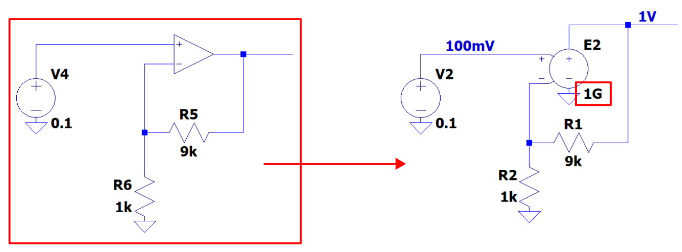
To emulate an ideal operational amplifier, we will take a non-inverting opamp circuit and replace the operational amplifier with our voltage-dependent voltage source as shown in the image below.
We have setup the feedback resistors in the non-inverting opamp circuit to have a gain of 10. To make the voltage-dependent voltage source act like an ideal operational amplifier, we have set its gain to something ridiculously high like 1G.
After performing the DC operating point simulation, we get the expected:
Vout = Gain × ( Vinp - Vinm ) = 10 × ( 0.1V - 0V ) = 1V
Less Ideal Operational Amplifier
Now that we have the voltage-dependent voltage source setup in the non-inverting amplifier circuit we can play around with operational amplifiers with less than ideal gains. Lets look at two different operational amplifiers and their low frequency, small signal gains:
MCP6001: 110dB or 320k V/V gain
LMV321: 70dB or 3.2k V/V gain
We will also change the feedback resistors to give us an ideal gain of about 1000.
(note we also decreased the input voltage to 1uV. However because we are using a voltage-dependent voltage source, we didn’t actually need to do this)
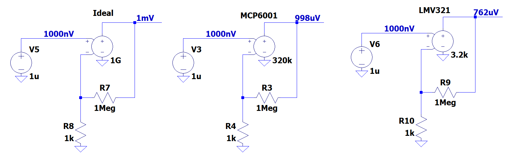
From the above image we see that:
Ideal circuit had amplified to 1uV input voltage to 1mV -> 1000 V/V gain
MCP6001 circuit had amplified to 1uV input voltage to 0.998mV -> 998 V/V gain which is a 0.2% gain error
LMV321 circuit had amplified to 1uV input voltage to 0.762mV -> 762 V/V gain which is a 24% gain error
Suppose you needed a circuit with less than 1% gain error, you could use this voltage-dependent voltage source opamp circuit to give you a rough idea of how much gain your opamp needs to accomplish this task.
Answer: at least 90k V/V or 100dB